|
|||||||||||||||
|

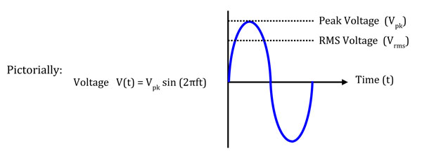
Amplifier Power, Voltage and Current ConsiderationsPower amplifiers for use at microwave frequencies are specified in Watts or the decibel (dB) equivalent of Watts (dBm or dBW), are almost always designed and specified for use with a 50 Ohm2 load impedance. There are instances where the voltage and/or current associated with a given power level are needed. Calculating the voltage and current for a given power can be easily done using the Ohm’s law equations or by using one of the many “Ohm’s Law” calculators that can be found on the internet. Ohm’s law relates voltage (V), current (I), resistance (R) and power (P). The equations states V = IR and P=IV. With substitution, we get V2 = RP or V = √(RP) and I2 = P/R or I = √(P/R) Example: for 10 Watts into 50 ohms, an amplifier has to provide 22.4 Volts and .45 Amps. For sine waveforms, these values of power, voltage and current are RMS (root mean square) values. The RMS value of a sine wave is the value equivalent to the DC (Direct Current) value that would product the same power as given by Ohm’s law. If a sine wave is given as V(t) = Vpk sin (2πft), the RMS value Vrms is Vpk/√2 = 0.707Vpk So in our example above, for 10 Watts into 50 Ohms, Vpk = 32 Volts and Ipk = 0.63 Amps.
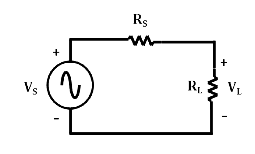
If an amplifier designed for driving a 50 Ohm load is presented with a lower impedance load, the current requirement increases and the voltage requirement decreases, and vice-versa for a higher impedance load. The amplifier’s voltage and current limitations can easily be exceeded if the load impedance varies significantly from 50 Ohms. Besides the voltage and current limitations of the amplifier, power delivered to the load is maximum at 50 Ohms for RF/Microwave power amplifiers. , This is because the amplifier’s input and output impedance are carefully designed to be as close to 50 Ohms as is reasonably possible. Consider the following circuit, with the amplifier modeled as a voltage source with source resistance RS of 50 Ohms, and a load resistance RL.
RS represents the output impedance of the amplifier with the amplifier providing voltage VS and current I. Intuitively, as the load RL decreases to zero, the voltage across the load decreases to zero, but the current is limited to VS/RS so that the power at the load decreases to zero as well. As RL increases to infinity, the current decreases to zero, but the voltage is limited to VS so that the power at the load decreases to zero again. The maximum power transfer is at the optimum balance of voltage and current. |
| Home | Company | Contact Us | Copyright © All rights reserved. | |||