|
|||||||||||||||
|

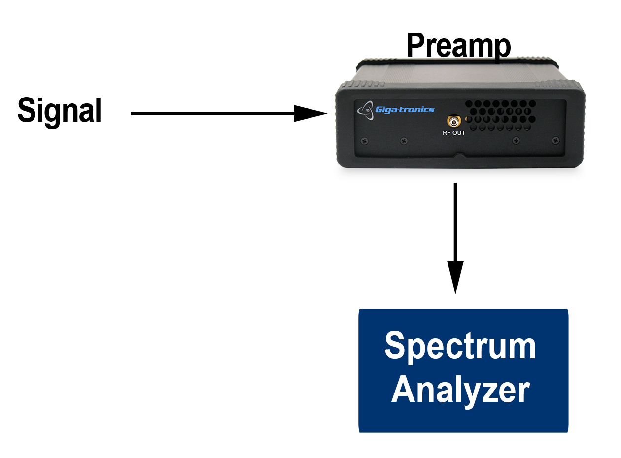
Amplifiers used as Pre-amps with Spectrum and Signal AnalyzersThe low noise figure, high gain and flat frequency response of the Spanawave/Giga-tronics amplifiers allow them to be used as preamplifiers for high noise figure spectrum and signal analyzers. The Spanawave/Giga-tronics amplifiers used as a preamp can help bring low level signals above the noise floor of the analyzer. The approximate formula for noise figure of cascaded amplifiers is calculated in linear terms of noise factor (F): Ftotal = F1 + (F2 - 1) / G1 Where F1 is the noise factor of the first amplifier, G1 is the gain of the first amplifier, and F2 is the noise factor of the second or following amplifier. Note that in the exact formula, there may be additional terms for additional amplifiers following the first two, but these terms are negligible if the gains are reasonably high, since the gains multiply in the denominator of additional terms. This can be written in terms of a preamp and analyzer: Fsystem = Famplifier + (Fanalyzer – 1)/GAINamplifier
The broad frequency range of the Spanawave/Giga-tronics amplifiers, from 100 MHz to 20 GHz, 40 GHz and 50 GHz, matches the frequency range of the majority of spectrum and signal analyzer applications. The Spanawave/Giga-tronics’ parallel-MMIC design provides wide linear range and a sharp saturation knee. The result is outstanding performance when used with signals having high peak to average ratios. The broad frequency range provides excellent pulse performance preserving the fast rise and fall times of high speed signals and narrow pulses. |
| Home | Company | Contact Us | Copyright © All rights reserved. | |||