|
|||||||||||||||
|

Doppler Radar Test
In war, conflicts and other military to military skirmishes we need to detect high velocity vehicles such as supersonic jet fighters. This in the past has driven how we optimized the performance of Radars and Electronic Warfare systems and their associated test equipment. While a requirement for this capability still exists, a great deal of modern uses of radar is for surveillance - be it monitoring factions in the Middle East, or analyzing unscrupulous activity occurring at countries borders – this means we have to deal with much slower targets, such as vehicles, mules and individuals. This changing requirement is observed more specifically in Doppler Radar Systems. These radars rely on the same effect observed as the apparent change in frequency or pitch when a sound source moves either toward or away from the listener, or when the listener moves either toward or away from the sound source. As we will discuss this theory not only applies to sound waves, but is equally applicable at microwave signal frequencies as well. For example - let’s look at military to military skirmish - if a hostile jet fighter is traveling head-on towards our radar at about 300mph and we illuminated it using a pulse transmitted in the X-band, say 10 GHz, we will see a difference in frequency from the original and the reflected of approximately 9 kHz to 10 kHz. The amplitude of the reflection of course is very small compared to that of our original signal, and to be able to detect it requires that the phase noise or frequency stability of the system synthesizer or Local Oscillator is not dominant at this reflection frequency. I picked this example specifically to outline that most microwave signal generators have some phase noise optimization around the 10 kHz offset frequency range. In fact most X-Band frequency synthesizers and microwave test equipment usually quote phase noise at a center frequency of 10 GHz with a 10 kHz offset. What if our hostile target is now a heavily laden donkey approaching our border on overcast winter night, or a convoy of vehicles in a desert sandstorm? At a maximum speed of about 10 mph, the Doppler frequency shift using the same X-band transmitter will be about 300 Hz. So if you’ve been tasked with designing the next generation of surveillance radars or a moving target indicator system (MTI), close to carrier phase noise is a critically important factor. (See Table 1).
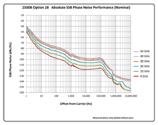
Table 1. Doppler Frequency Shift (Hz) versus Target Speed (mph) at 10 GHz Dissecting Phase NoisePhase noise refers to shortŌĆÉterm, random fluctuations in the phase of the signal, and is usually expressed as value normalized to a 1 Hz bandwidth and at some offset frequency away from the signal frequency and relative to the amplitude of the signal. It can be expressed as a number (for example ŌĆÉ115 dBc/Hz at 10 GHz and 10 kHz offset), but is also commonly shown as a graph of phase noise versus offset frequency for one or more signal frequencies. (See figure 1).
To understand the phase noise characteristics, let’s consider the key elements of a phased-locked-loop (PLL) based microwave signal generator, consisting of a frequency reference, the frequency synthesis block, typically followed by frequency multipliers.
Now taking these three elements into consideration - we can see that in Chart 1 each model of signal generators phase noise plots relatively follows the same curve. For offset frequency less than 1 kHz (what is often referred to as ‘Close-in’ Phase Noise) we see phase noise improves almost linearly with respect to the carrier offset. The instruments Reference circuitry play a large part in this part of the synthesizer’s performance. For offsets greater than 1kHz the ‘pedestal’ of noise is caused by the frequency synthesizer itself - this pedestal extends to the loop bandwidth followed by the noise of the free running oscillator. The latter usually drops monotonically at a rate of 20-dB per decade until it reaches the general broadband noise of the post-YTO amplification circuitry. Let’s compare this to some of the design criteria of 2500B series Microwave Signal Generators. First the reference needs to be stable - this is the fundamental contributor to close in phase noise. This goes beyond a good circuit or choice of Oscillator type, careful power supply filtering and mechanical design is also essential to reduce close in sidebands. Another interesting consideration when thinking about phase noise in the array of microwave signal generators available in the market today is the use of different loop bandwidths when locking to an external reference. A narrow bandwidth on the external frequency reference input can help minimize the effects of phase noise resulting from a noisy external frequency reference signal, while a wider bandwidth will allow more stable phase tracking of multiple signal generators - but that makes them more susceptible to phase noise from the external frequency reference. The Spanawave/Giga-tronics 2500B series overcomes this trade-off limitation by providing the capability to phase track using an internal 100 MHz oscillator with wide loop bandwidth while keeping a narrow bandwidth on the 10 MHz external frequency reference input. Comparing each plot, in Figure 3 we also see that the phase noise also degrades at higher frequencies. This is largely due to the effect of the frequency doubling circuits that theoretically can increase the phase noise up to 6 dB each time frequency is doubled. (It also decreases by 6 dB each time frequency is divided by two). The general formula is: L(fx) = L(fo) + 20 log n Where L(f) is the phase noise and n is the frequency multiplication (or frequency division) number. Looking at the figure 2 diagram, the 2500B series Microwave Signal Generators use a wide-range 4 GHz to 10 GHz YIG-tuned oscillator. Then, 10 GHz to 20 GHz is provided by x2 multiplication, 20 GHz to 40 GHz by x4 and 40 GHz to 50 GHz by x6. What this means, and can be seen in the charts, is the 2500B series phase noise performance at 40 GHz or 50 GHz has been kept as low as possible. For the designer of a Doppler Radar - who needs to extrapolate slow moving targets from ground or sea clutter, and a core design goal for the Spanawave/Giga-tronics 2500B family of signal generators – has been to generate this relatively high fundamental frequency range, (4 GHz to 10 GHz), thus minimizing the amount of doubling required to achieve >10 GHz, 20 GHz, 40 GHz and ultimately 50 GHz.
ConclusionDoppler radar relies on detecting frequency changes. The emerging surveillance radar market requires that we can extrapolate slow moving targets from land clutter. This means that the radar has to deal with smaller and smaller frequency changes. Modern microwave signal generator design needs to take this evolving requirement into account and incorporate both a very stable frequency reference combined with the ability to synthesize signals at higher and higher frequencies thus reducing the need for frequency doubling and keeping close-in phase noise to a minimum. |
.png)
.png)
| Home | Company | Contact Us | Copyright © All rights reserved. | |||